LMP-01/02/01N
In vitro cardiac perfusion system with working heart option, Langendorff, Janiczky and Neely
In vitro cardiac perfusion system with working heart option, Langendorff, Janiczky and Neely
The LMP-01/02/01N In vitro cardiac perfusion system is characterised by a high degree of modularity, which increases the application possibilities, and its space requirements are very favourable.
Optional:
LMP-01 one-column and LMP-02 two-column Langendorff system

In the following, the main components of the system are presented in order of priority of their functionality, based on the overall Figure I.
Ensuring the temperature and pressure inside the system for optimal functioning of the heart preparation
Circulation of a physiological solution (Krebs), gas input (carbogen) into the system
![]()
LMP-01N Working Heart option according to Neely
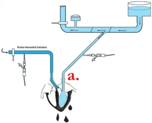
The modular advantage of the system is further enhanced by the fact that the Neely working heart option can be cost-effectively and technically easily constructed by replacing the glass elements on the left side of the rack. The process flow diagram above illustrates the Working Heart model in principle. The one on the right shows the system developed based on this conceptual arrangement.
The advantage of using the Neely working heart model over the Langendorff method, as shown in the figures, is that it models blood flow under in vitro conditions, creating a much more physiological mode of operation.
In the model, the perfusion solution (e.g. Krebs) enters the left atrium via the pulmonary vein and is pumped out through the left ventricle and aorta against a resistance, thus modelling the systemic vascular resistance of the body. Furthermore, this design allows the heart to produce a physiological pumping action under in vitro conditions.
A fundamental requirement for the system was to maintain the optimal physiological state of the preparation (heart) during prolonged operation. Taking this condition into account, the mechanical and glass engineering units were designed and connected to the operation.

1. Heart holder/organ chamber unit
The figures above illustrate one of the most integrated units of the system, which consists of three elements. The aim is to fix the preparation quickly and with the least damage and to ensure stable physiological conditions.
The double wall ensures thermal stability.
Aorta unit
The figure illustrates the elements of the unit and the process of perfusion after completion of the Langendorff module.
Atrium unit
Figure illustrates the elements of the unit and the process of retrograde perfusion.
Eight-point extra cellular MAP sensor
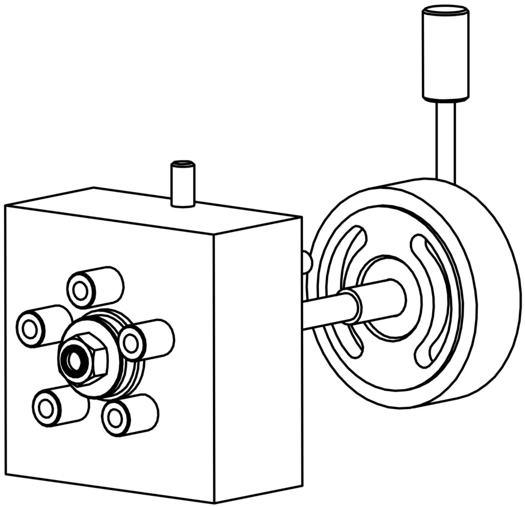
The 8-point non-invasive measurement is a unique development of our company. The preparation is placed in a physiological solution in the organ dish and surrounded by a specially designed MAP sensor. The MAP waves of the preparation are detected by the sensors through the solution. The sensors can be fitted to any standard extracellular force input.
Additional service: mechanical attachment of a stimulating electrode can be provided on request.
Optional accessories
CWB-20
20l circulating water bath
HC-B
Pressure and temperature meter
Stimulating electrode
PC-B
Pump controller
Recommended MAP amplifiers for extra cellular signal processing
We can recommend systems that can be used to amplify physiological MAP signals:
Recommended software
We recommend the following software/hardware systems for the display, storage and analysis of the curves of the measured physiological parameters:
| TECHNICAL FEATURES | LMP-01/02/01N |
|---|---|
| Application | In-vitro heart perfusion working heart system according to Langendorff, Janiczky and Neely |
| Testable organ types | Mouse, rat, guinea pig, rabbit isolated heart |
| Easy to switch between Langendorff and working heart modes during measurement |  |
| Easy mounting of the preparation on the heart holder |                  |
| Organ holder with stimulation | Space or point stimulation with electrodes |
| Mobile heart reservoir and heart holder cannula |                  |
| Pressure and temperature sensors located directly at the heart |                  |
| Gas pre-storage |                  |
| Gas fine control system |                  |
| Janiczky balloon working heart measurement |                  |
| Replacement of glass and heart support with working heart measurement according to Neely |                  |
| Constant flow or constant pressure mode with pump control |                  |
| Temperature stability directly at the heart connection 0,1C° |                  |
| Dimension | 600×800×850mm |
| Vibration-proof stand |                  |
| Weight | 10kg |
| Thermostation (Optional) | CWB-20 External thermostat: 20l capacity, 30l/min. delivery rate, 0,1C° accuracy |
| Stimulating electrode (Optional) |                  |
| Pressure and temperature meter (Optional) | HC-B |
| Extra/Intra-cellular MAP measurement (Optional) | EXT-04 |
| Pressure flow regulator (Optional) | PC |
| TECHNICAL FEATURES | CWB-20 thermostat |
|---|---|
| Application | Circulation water bath thermostat |
| Temperature display | LED number display 3 digit |
| Temperature sensor | Semiconductor |
| Temperature control | Automatically with comparator on/off switching |
| Temperature setting | Analogue mode continuous |
| Pump delivery capacity | Maximum 30l/min |
| Working temperature range | Room temperature … +40°C |
| Temperature stability | ±0,01°C |
| Maximum capacity of the tank | 20l |
| Power input | 1300W |
| Dimension | 320×350×220mm |
| Weight | 10kg (without liquid) |
| Power supply | On request: 110V or 220V, 50/60 Hz |
| TECHNICAL FEATURES | PC-B |
|---|---|
| Application | Peristaltic pump contoller |
| Pressure input resistance | 10k Ω |
| Pressure meter calibration | 1V = 100Hgmm |
| Regulation type | PI |
| Regulator output range | 0 … 5V 0 = 0 … 100% |
| Pump on/off control output |                  |
| Set desired pressure value |                  |
| Weight | 1kg |
| Power supply | On request: 110V or 220V, 50/60 Hz |
| TECHNICAL FEATURES | HG-B |
|---|---|
| Application | Two-channel pressure and temperature meter |
| HG Amplification | 10 000, continuously adjustable |
| HG Bandwidth | DC, 200Hz* |
| HG Calibration levels | GND, 1V |
| HG Bridge voltage | On demand |
| HG Offset | ±1V (100Hgmm) relative to output |
| HG Display | LED band |
| HG Input impedance | 10MΩ symmetric |
| HG Output impedance | 100Ω asymmetric |
| HG Value conversion | 100Hgmm = 1V |
| TH Bandwidth | DC, 5Hz* |
| TH Calibration levels | GND, 45°C (450mV) |
| TH Bridge amplification | On demand |
| TH Display | LED number display 3 digits |
| TH Input impedance | 10kΩ symmetric |
| TH Output impedance | 100Ω asymmetric |
| TH Sensor type | PT1000 |
| TH value conversion | 10°C = 0.1V |
| Temperature accuracy | ±0,1°C |
| Power supply | On request: 110V or 220V, 50/60 Hz |
| *HG = pressure meter, TH temperature meter |
| TECHNICAL FEATURES | Stimulating electrodes |
|---|---|
| Application | Ventricular stimulating electrode |
| Fixation with manipulators |                  |
| Maximum voltage | 150V |
| Shaded cable |                  |
| Diameter | 2mm |
| Length | 150mm |
| Weight | 220g |
| Wire length | 500mm |
| Weight | 200g |


