IOB-04/08
in vitro isolated organ bath for tissue slices
in vitro isolated organ bath for tissue slices
The system is characterised by a unique modularity that provides the possibility to:
Optional:
Three independent circuits ensure stable physiological functioning:
Structure
The main advantage of the system is that it is made up of three independent mechanical blocks on a common support rack, which are connected by a pipe system:
The advantage of this solution is that it significantly facilitates installation, maintenance and repair of the system in the case of a malfunction, as well as its expansion on demand.
Organ chamber block
The block consists of two mechanical supports:
The two elements can be mounted in a block on the support rod of the rack system that holds the blocks.
The two elements can be moved relative to each other to position and lock them on the support rod. This positioning ensures that the organ holder, and thus the tissue preparation under test, is optimally positioned within the organ chamber.
The organ chamber containment element includes a fine adjuster for the carbogen gas and a two-position tap through which the organ chamber can be filled with physiological solution from a buffer reservoir.
The incubation and experimentation of the tissue preparation is done in the organ chamber. Successful implementation requires that the organ chamber and the elements described above are harmonised according to the purpose of the experiment.
Organ chamber
1. Physiological solution inflow
2. Overflow, over wash
3. Reservoir emptying
4. Thermostatic solution inlet
5. Thermostatic solution outlet.
Gas (carbogen) inflow regulation
The gas (e.g. carbogen) that is introduced into the physiological fluid space of the organ chamber is essential to ensure the physiological conditions of the tissue preparation, but the physical state of this gas in the fluid space is not a negligible factor in addition to this function. If this gas is introduced into the fluid space by inappropriate nebulisation, it can cause very substantial mechanical movement, which negatively affects the test results.
For this purpose, our company has developed a three-step control cycle.
Step 1: From the cylinder, the gas is transferred to a central collecting buffer space (see system figure). From this space, it branches out into the organ holder and buffer blocks.
Step 2: It enters the hollow space of the mechanics enclosing the organ chamber via A stub and moves on to the next block via B stub.
Step 3: It then passes through valve C to the fine regulator, where a cylinder controlled by a fine spindle adjusts the gas line cross-section. From the valve, it passes to the organ holder for final atomization and enters the fluid space.

Organ holder
The function of the organ holder in the block is to precisely position the tissue strip (e.g. to prevent sticking, etc.), calibrate the capacity of the organ chamber, ensure gas atomization with the correct bubble size. An essential function is to ensure homogeneous spatial distribution of the correct input of the stimulus current.
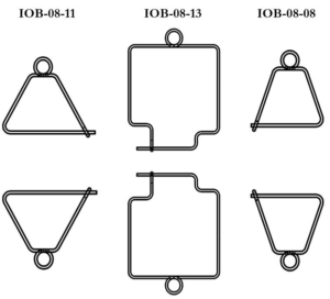
A. Organ suspension hook
B. Current stimulation electrode pair
C. Holder for the mechanical fixing element
D. Gas input tube with nebulizer pipe (d.).
Two types of baffles are made for the current induction in each of the diameters given above.
For both types of electrodes, we produce elements suitable for the suspension of the vascular ring preparation.

Sensor support block
The block is positioned directly above the organ chamber block and is fitted with a replaceable sensor support element 1 mm thread pitch single-plane spindle tension manipulator.
Regardless of the force/displacement sensor FSG-01, as shown in the figure, MSB-MET can adapt the sensor element 
to any customer’s requirements, provided that the appropriate documentation is available.
Basic physical parameters:
Buffer block
Organ suspension – pre-load
In developing the components of the system presented here, the aim was to get the organ under test into the measuring field (organ chamber) as quickly as possible and with the least damage. This objective is served by the coordinated operation of the sub-assemblies.
Step 1.
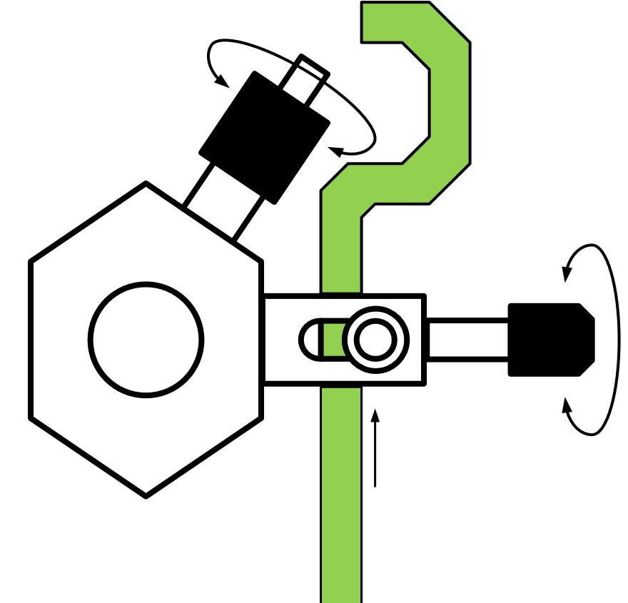
The organ chamber is removed from the organ block by loosening the organ chamber retaining screw. The block is slid down the support rod until the holder is free. The block is then fix to the rod.
Step 2.
One end of the prepared tissue strip is attached to the lower hook of the organ holder and the other end to the arm of the force/displacement sensor.
Step 3.
Loosen the retaining screw of the organ chamber support block and move the holder back into the organ chamber by sliding it up the support rod.
Step 4.
As a result of the operation, the holder and the attached tissue slice are immersed in the carbogenised solution filling the reservoir. In this step, the holder calibrates the volume of the solution in the reservoir by displacing excess solution. The excess is removed through the overflow stub of the reservoir.
Optional accessories:
CWB-20
20l circulating water bath
FSG-01
Force/displacement sensor
SG-04
4-Channel bridge amplifier
Recommended software
We recommend the following software/hardware systems for the display, storage and analysis of the curves of the measured physiological parameters:
| TECHNICAL FEATURES | IOB-04/08 |
|---|---|
| Application | In vitro isolated organ bath for tissue stripes |
| Testable tissue types | digestive (stomach, small and large intestine sections) endometrium (pregnant, non-pregnant, slices) uterine (cervix) rings vascular rings (vein, artery, coronary artery) ciliary muscles of the eye penis corpus cavernosum smooth muscle |
| Exchangeable organ chambers | Replaceable service containers (5, 10, 20 ml calibrated capacity) |
| Expandability | Quick expandability to 2, 4, 8 channels |
| Stimulation of organ holders | Space or point stimulation with electrodes |
| Organ holders |  |
| Vessel ring holders | From Ø 0,8mm designed for built-in stimulating electrodes |
| Gas pre-storage |      |
| Gas fine control system |      |
| Manipulators | Single-plane self-adjusting tensioner with 500µm sensor fixture |
| Buffer reservoir | 0.4l. 1.5l per channel, with optional capacity |
| Vibration-proof stand |      |
| Weight: | 10kg |
| Thermostatic (Optional) | CWB-20 External thermostat: 20l capacity, 30l/min. delivery rate, 0.1C° accuracy |
| Force/displacement sensor (Optional) | FSG-01 sensor: 50g, 100g, 200g, 500g. |
| Displacement measuring amplifier (Optional) | SG-04 4-channel bridge amplifier |
| TECHNICAL FEATURES | CWB-20 thermostat |
|---|---|
| Temperature display | LED number display 3 digit |
| Temperature sensor | Semiconductor |
| Temperature control | Comparator with on/off switching automatically |
| Temperature setting | Analogue mode continuous |
| Pump delivery capacity | Maximum 30l/min |
| Working temperature range | Room temperature … +40°C |
| Temperature stability | ±0,01°C |
| Maximum capacity of the tank | 20l |
| Power input | 1300W |
| Dimension | 320×350×220mm |
| Weight | 10kg (without liquid) |
| Power supply | On request: 110V or 220V, 50/60 Hz |
| TECHNICAL FEATURES | FSG-01 |
|---|---|
| Input/output resistance | 400 Ω |
| Max. power supply | 7V DC |
| Recommended power supply | 4V DC |
| Diameter | 22mm |
| Length | 75mm |
| Weight | 220g |
| Maximum lever deviation | ± 10mm |
| Linearity | Maximum. 1% error at 94% of maximum deviation |
| Weight | 200g |
| TECHNICAL FEATURES | SG-04 |
|---|---|
| Amplification | × 10 000, continuously adjustable |
| Bandwidths | DC, 200Hz* |
| Calibration levels | GND, 1V |
| Bridge voltage | On demand |
| Offset | ±6V relative to output |
| Display | LED bar |
| Filtering | Switchable: OFF, 3Hz, 10Hz, 40Hz, (40dB) |
| Input impedance | 10MΩ symmetric |
| Output impedance | 100Ω asymmetric |
| Power supply | On request: 110V or 220V, 50/60 Hz |


